Project Detail
Warning: Trying to access array offset on false in /home/hagorbuk/ge-hydro.work/wp-content/plugins/wp-google-map-gold/modules/shortcode/views/put-wpgmp.php on line 1799
Halhal Small-Scale Earth Dam Construction (Dam Mikilim)
In 1997, the Ministry of Agriculture (MOA) initiated the construction of an earth dam in Halhal village, located in the Anseba region of Eritrea. The primary objective was to conserve water for irrigation, enabling the village farms to benefit either directly from the reservoir or indirectly through the replenishment of the local groundwater system.
Construction Period
The construction spanned from February 1997 to June 1997, involving approximately four months of intensive work to complete the project.
Location
Halhal village, Anseba region, Eritrea.
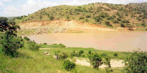
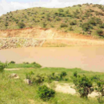
Figure 1 provides an aerial view of the reservoir, showcasing its layout and surrounding area.
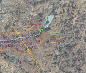 Figure 1: Halhal Small-Scale Earth Dam, Mikilim Dam (Google Image).
Enterprise
The project was undertaken by the Ministry of Agriculture (MOA), headquartered in Asmara, the capital of Eritrea. This governmental organization operated through six regional and numerous sub-regional offices, coordinating agricultural development across the country.
Method of Construction
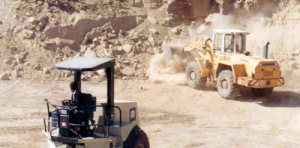
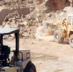
The construction process involved the use of various heavy machinery, including rollers, loaders, bulldozers, and graders. Additionally, loading trucks and pickup vehicles were employed for transportation and logistical support throughout the project.
Responsibilities
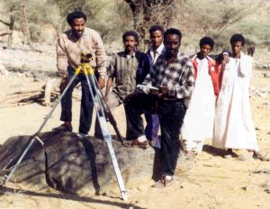
The primary responsibility was to construct the dam while also overseeing the development of other small-scale diversion structures in nearby areas. One such project included the construction of a small weir in the Asmat area, designed to redirect flash floods into a basin irrigation system.
Figure 2 illustrates the survey conducted for the Asmat irrigation project, showcasing the strategic planning and execution involved in enhancing local water management infrastructure.
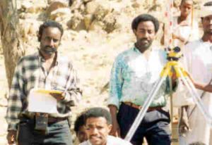
Figure 2: Photo Taken at Asmat Irrigation Project, 1997.
The Halhal Dam was designed with the following specifications:
- Height: 17 meters
- Crest Length: 65 meters
- Crest Width: 5 meters
- Base Width: Approximately 90 meters
The core of the dam was constructed using clay soil, providing impermeability, while the upstream and downstream surfaces were reinforced with compacted soil excavated from the reservoir area. The slopes of the dam were designed with a ratio of 1:3 (upstream) and 1:2 (downstream), ensuring stability and durability. Both surfaces were protected with stone rip-rap to resist erosion, and the downstream face included a berm positioned at mid-slope to further enhance structural integrity.
Gravel and Sand Filtration System
At the toe of the dam’s downstream side, a sand and gravel filtration system was installed. This system plays a critical role in safely discharging water from the phreatic line, reducing pressure, and ensuring the stability of the dam structure.
Figures 3 and 4 illustrate a typical earth dam profile and the process of placing the gravel filter during the construction of the Halhal Dam.
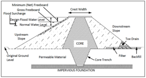
Figure 3 Typical example of earth dam profile.
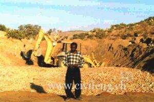
Figure 4 Gravel filter lying, Halhal.
Spillway
The spillway was a simple excavation with a width of approximately 10 meters and a depth of 1.5 meters. It extended downstream along the natural course of the existing river, as shown in Figure 1. The freeboard level of the dam was set at 15.5 meters above the base, meaning the maximum water depth in the reservoir was also 15.5 meters. The reservoir’s fetch length extended over 120 meters toward the upstream boundary of the reservoir.
Outlet Structure
The outlet was constructed using a standard concrete pipe, protected by a reinforced concrete cover for added durability. To reduce water seepage (creep), the pipe was equipped with 11 collars, spaced 7 meters apart. These collars played a critical role in maintaining the integrity of the structure by minimizing the risk of water infiltration along the pipeline.
Figure 5 depicts the type of collars used for the Halhal Dam’s outlet structure. While the image is sourced from the internet, it accurately represents the design and functionality of the collars implemented in the project.
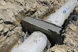
Figure 5 Seepage protection collar.
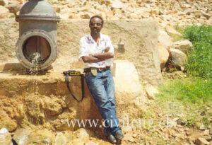
The outlet structure at Halhal is depicted in Figures 6 and 7.
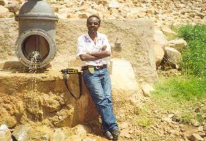
Figure 6 Halhal outlet structure (photo taken just after the construction ended).
The exterior end of the outlet structure, constructed with a metal pipe connecting the valve to the concrete pipe, is shown in Figure 7.
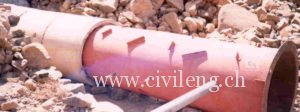
Figure 7 Valve and concrete pipe connector used at Halhal dam.
Foundation
The foundation along the central axis of the dam was excavated and subsequently filled with clay soil, extending up to the freeboard level. Figure 8 illustrates the construction process of the dam at Halhal.
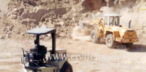
Figure 8 Construction of Halhal earthdam (Dam Mikilim).
Compaction
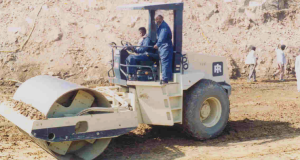
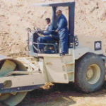
The compaction process was carried out using two rollers. The method involved rolling back and forth four times over a 0.3-meter-thick layer of soil while simultaneously applying water to aid in compaction. A bulldozer was used to evenly distribute the soil across the surface, after which the rollers compressed it thoroughly. Figure 9 depicts the compaction process during the construction of the Halhal Dam.
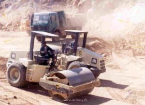
Figure 9 Compaction of Halhal dam.
Hydrological Studies
The hydrological study for the dam was conducted using approximate empirical methods. It was estimated that 10% of the annual rainfall contributed to runoff. The runoff volume was then calculated by multiplying the runoff depth by the catchment (watershed) area, providing a straightforward estimate of the water available for storage.
Project Cost
As a government-funded project, the detailed cost breakdown can be obtained from the relevant government bureau. However, an approximate evaluation of the costs can be made based on the machinery and personnel involved during the construction period.
Machinery and Operations
The following equipment operated 8 hours per day on weekdays throughout the construction period:
- Two compactors
- One loader
- One excavator
- Two bulldozers
- One grader
- Water tank trucks
- Two pickup vehicles
- Two loading trucks
Personnel
The construction team included:
- One trained engineer
- One foreman
- Two machinery foremen
- Machine operators for each piece of equipment
- Approximately 20 laborers and craftsmen
Estimated Costs
Excluding material costs (e.g., fuel, cement, sand, reinforcement bars, concrete pipes, and vehicle maintenance), the labor costs alone exceeded approximately 1 million Nakfa (~$71,428.57), based on the monthly salaries of the personnel involved.
The Role of Site Engineers
The site engineer had a pivotal role, which included:
- Regulating concrete mix and ensuring proper soil type usage
- Assisting foremen in interpreting construction drawings
- Controlling compaction processes and organizing machinery and construction materials
- Preparing the reinforcement bar schedule
- Translating the design into ground implementation
- Guiding excavation activities and supervising overall construction progress according to the plan
Workforce Involved
The construction team comprised skilled and unskilled personnel, including:
- One trained engineer
- Carpenters and masons
- Unskilled laborers
- Machinery operators and foremen
Key Project Details
- Location: Halhal, Anseba region, Eritrea
- Type: Earth dam
- Height: ~17 meters
- Crest Width: ~5 meters
- Crest Length: ~65 meters
- Spillway (Earth): Width of 10 meters
- Dam Profile Slopes: Upstream 1:3, Downstream 1:2
Link to the current status of the dam


